harmony 鸿蒙LED Peripheral Control
LED Peripheral Control
Overview
Based on the Hi3861 platform, the OpenHarmony WLAN module provides abundant peripheral operation capabilities, including the I2C, I2S, ADC, UART, SPI, SDIO, GPIO, PWM, and flash memory. This document describes how to control GPIO pins by calling the OpenHarmony native development kit (NDK) interface to implement LED blinking. For details about how to control other IoT peripherals, see the API guide.
Development
Complete the operations related to the mini system described in Quick Start Overview.
LED control examples are stored in the file applications/sample/wifi-iot/app/iothardware/led_example.c.
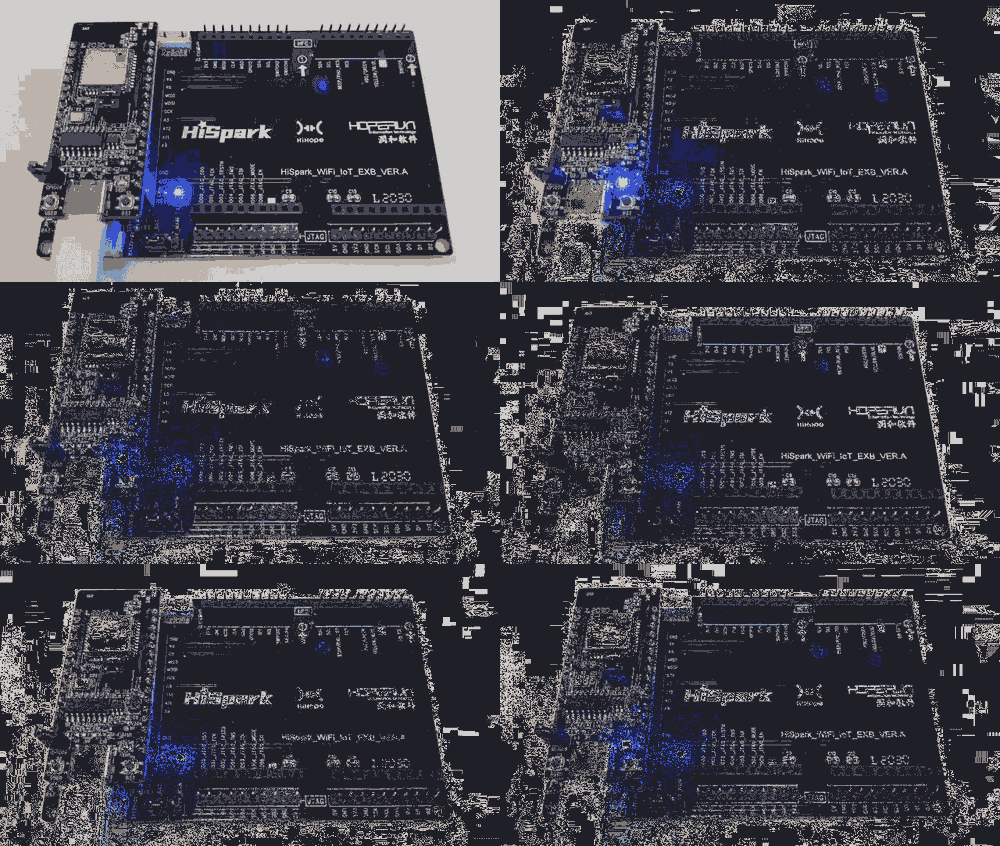
Understand the cable connections by referring to the schematic diagram of the development board. You can learn that LED of hispark pegasus is connected to pin 9 of the chip.
#define LED_TEST_GPIO 9 NOTE
NOTEFor details about the schematic diagram of the development board, contact the Hi3861 customer service personnel.
Initialize the GPIO pin, specify the pin usage, and create a task that turns on or off the LED periodically to implement LED blinking.
static void LedExampleEntry(void)
{
    osThreadAttr_t attr;


    /* Initialize the GPIO pin. */
    IoTGpioInit(LED_TEST_GPIO);
    /* Set pin 9 as the output direction. */
    IoTGpioSetDir(LED_TEST_GPIO, IOT_GPIO_DIR_OUT);


    attr.name = "LedTask";
    attr.attr_bits = 0U;
    attr.cb_mem = NULL;
    attr.cb_size = 0U;
    attr.stack_mem = NULL;
    attr.stack_size = LED_TASK_STACK_SIZE;
    attr.priority = LED_TASK_PRIO;


    /* Start the task. */
    if (osThreadNew((osThreadFunc_t)LedTask, NULL, &attr) == NULL) {
        printf("[LedExample] Failed to create LedTask!\n");
    }
}
Use a cyclic task in which the LED periodically turns on and off to implement LED blinking.
static void *LedTask(const char *arg)
{
    (void)arg;
    while (1) {
        switch (g_ledState) {
            case LED_ON:
                IoTGpioSetOutputVal(LED_TEST_GPIO, 1);
                usleep(LED_INTERVAL_TIME_US);
                break;
            case LED_OFF:
                IoTGpioSetOutputVal(LED_TEST_GPIO, 0);
                usleep(LED_INTERVAL_TIME_US);
                break;
            case LED_SPARK:
                IoTGpioSetOutputVal(LED_TEST_GPIO, 0);
                usleep(LED_INTERVAL_TIME_US);
                IoTGpioSetOutputVal(LED_TEST_GPIO, 1);
                usleep(LED_INTERVAL_TIME_US);
                break;
            default:
                usleep(LED_INTERVAL_TIME_US);
                break;
        }
    }
}
Call SYS_RUN() of OpenHarmony to start the service. (SYS_RUN is defined in the ohos_init.h file.)
SYS_RUN(LedExampleEntry);Add led_example.c to the applications/sample/wifi-iot/app/BUILD.gn file for building.
import("//build/lite/config/component/lite_component.gni")
lite_component("app") {
    features = [
        "iothardware:led_example"
    ]
}
Verification
For details about the compilation and burning processes, see Building Source Code and Burning an Image.
After the preceding two steps are complete, press the RST button to reset the module. If the LED blinks periodically as expected, the verification is passed.
你可能感兴趣的鸿蒙文章
harmony 鸿蒙Development Examples
harmony 鸿蒙Screen and Camera Control Overview
harmony 鸿蒙Debugging and Packaging
- 所属分类: 后端技术
- 本文标签:
